A Simpler Approach to Liquid Handling Robotics in Parallel Synthesis
Philip F. Hughes,* Matthew S. Clapham+ and Thomas H. Graham#Lilly RTP Labs, Lilly Research Laboratories, Eli Lilly & Company, 20 T. W. Alexander Drive, Research Triangle Park, North Carolina 27709
*Corresponding author: Philip F. Hughes, 627 Arlington Street, Chapel Hill, NC, 27514. Email : pfhughes@nc.rr.com
+Current address: Novartis Institutes for Biomedical Research, Inc., 254 Massachusetts Ave. Cambridge, MA 02139
# Current address: University of Pittsburgh, Department of Chemistry, 234 Chevron Science Center, Pittsburgh, PA 15260.
Robot moviesyou can look at.
Abstract: We describe a general concept for the use of liquid handling robotics in parallel synthesis and its implementation in hardware and software on two TECAN platforms. The system, called "Transfer," allows rapid setup and execution of standard organic synthesis operations in array formats. Such operations include extractions, filtrations, removal of aliquots for chemical analysis, spotting of TLC plates, transfers and reagent addition. The speed of setup and operation coupled with ease of use of the Transfer system makes it amenable to use in a medicinal chemistry environment involved in parallel synthesis.
Introduction. Over the last ten years our laboratory has been developing and using high throughput synthesis for support of lead generation and lead optimization efforts. Generally, we have run reactions in custom 24 and 96 well reactors1 in a microtiter plate format. Although we use manual methods and gadgetry2 for many tasks, liquid handling robots have proven indispensable for workups and analysis. We have developed a robotics software system, called "Transfer," that allows medicinal chemists to quickly learn the robots operation (15 minutes training) and even more quickly (< 1 min.) set up the robot and start a task. To date, we are not aware of robotic systems, commercial3 or otherwise, that operate in a similar manner. We describe here the underlying principles for our approach and the implementation and operation of this software. We also describe minor robotic hardware modifications.
Results and Discussion. The automation needs in a synthetic chemistry lab are very different from those in a high throughput screening lab. In a screening lab, robots are set up to perform one, possibly complex, task repeatedly over a long period of time, say a month. In a synthetic chemistry lab we imagined the robot performing a wide variety of different tasks, each requiring only a few minutes. For example, one chemist might use the robot to spot 48 samples on a TLC plate and, twenty minutes later, a different chemist would use the same robot to do 24 liquid-liquid extractions, followed by yet another chemist who wants to remove 96 aliquots for LC/MS analysis. Is there a single mechanism that covers all these tasks and can it be coded into a simple user interface?
At the simplest level, the tasks described above can be reduced to a few instructions shown in Figure 1. The robot tip moves to a vertical position (z1) in a source tube (position x1, y1), removes liquid (Volume), then moves to a vertical position (z2) in a destination tube (position x2, y2) and dispenses the liquid (Volume). So the user only has to set two vertical heights, a volume and the tubes on which to perform the operation. For example, to perform an ethyl acetate/water extraction, the z1 position is set to just above the meniscus in the source tube, the volume is set to slightly more than the ethyl acetate volume in the tube, the z2 position is set just inside the top of the destination tube and all the tubes in an array are chosen for the operation. The robot tip goes to position x1,y1 at height z1, pulls the specified volume, moves to position x2, y2 at height z2, expels the liquid and then moves to the next tube to do the same thing. This works if the tubes are to be all treated the same way and there is a one-to-one mapping of source tubes to destination tubes. Fortunately, this is generally the case in parallel synthesis. The x and y positions are fixed by the reactor geometry and the vertical positions and volumes are constant for any one task but can be highly variable from task to task.
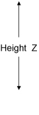
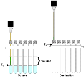
Figure 1. Robots move a liquid (Volume) from a height (z1) in one well (source; x1, y1) to a height (z2) in another well (destination; x2, y2).
So the challenge is figuring out how to quickly and easily set a new deck layout, heights (z1 and z2), volumes and sample selection for each different use. The optimal method for setting each of these parameters is different, but when possible, a visual or graphical method usually works best. For example, to set the heights, the chemist could use the software to physically drive the tip to the desired position. It is also important that changing frequently modified parameters be more obvious than changing parameters often left as default. With these considerations in mind, we describe our implementation of a robotics control system for the TECAN MiniPrep 75/1,4 commercial liquid handling robot.
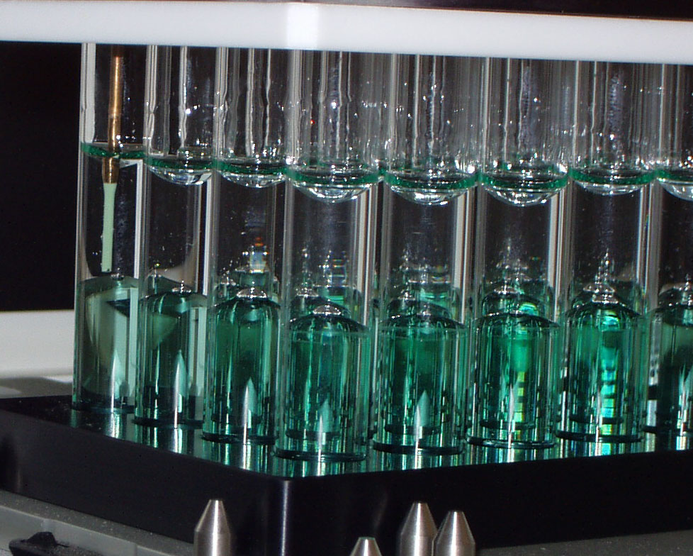
The TECAN MiniPrep 75/1, shown in Picture 1., is a conventional one-arm single tip liquid handling robot and is used with some modification. The robot is purchased with two syringe drives and a 6-way solvent selection valve. The two syringes (250 uL and 5 mL) are plumbed in parallel to allow fine and course pipetting control. A 10 mL loop is inserted between the syringes and the tip to allow aspiration of larger volumes without valve contamination (See Figure 2.). The waste lines are plumbed with Teflon tubing for solvent resistance. Low profile custom rack carriers are used to maximize utilization of the robot height (z travel range).
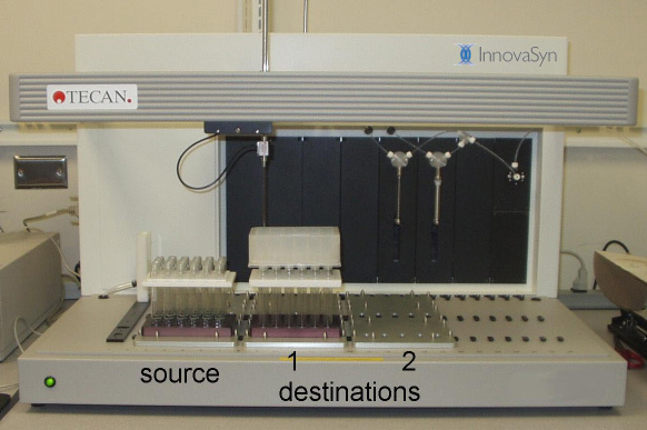
Picture 1. Tecan MiniPrep 75 performing an extraction, by removing the top layer from one plate of reactor vials and passing the solution through a filter plate into a new plate of vials.
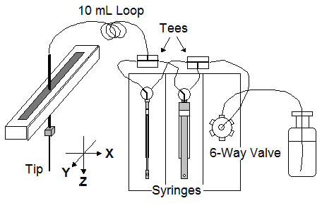
Figure 2. Plumbing schematic for the TECAN MiniPrep 75/1
A picture of the "Transfer" software screen is shown in Figure 3. Control 1 is a pulldown menu used to select the worktable for an operation, in this case a 24 well to 24 well transfer. The screenshot (Figure 3.) shows the controls (2-5) available for that operation. Controls 2 set the height (z) for the source and the heights (z) and volumes for two destinations. Controls 3 set a number of special parameters that are usually left as default. Controls 2 and 3 will be explained in more depth later. Control 4 is a graphic showing the layout of the robot deck. Racks 1-3 are the source racks and Racks 4-9 are the destination racks. Transfers usually go across and the one to one mapping requires that a transfer from well A1 of source Rack 3 will go only to well A1 of destination Rack 6 and/or Rack 9. Finally, Controls 5 are used to select the source samples that will be transferred. Well selection is made by standard Windows mouse controlled combinations. A click-and-drag to select the entire rack is the most commonly used. The well color changes from white to green upon selection.
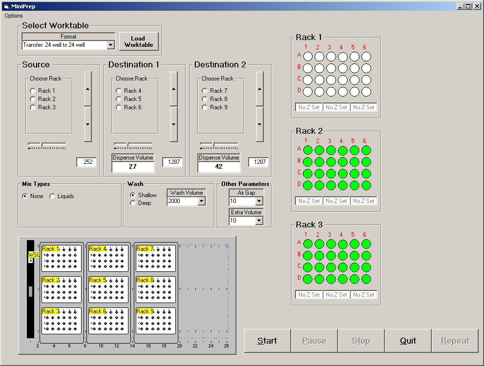
Figure 3. Screen shot of Transfer interface with 1.) Worktable selector control 2.) Controls for setting "Z" and Volume for Source and two Destinations 3.) Special controls 4.) Worktable graphic and 5.) Sample selection controls.
An example of the use of the 24 well to 24 well transfer is shown in Picture 1. The robot is performing an extraction by removing the top layer (the organic layer) from the source plate and passing it through a filter plate containing drying agent into a receiving plate. Only destination 1 is being used.
Operation of the Z and Volume control (Control 2) is explained in Figure 4. To set the height to deliver solution into a plate at rack position 6, the chemist would select the button for Rack 6, as defined in the layout graphic. The tip moves to position A1 of the plate, but stays at the maximum height to avoid any collisions. The chemist then drives the tip down to the desired position using the arrow buttons. The arrow buttons operate with a parabolic response such that if the chemist hits the button at the extreme top or bottom, one gets the maximum incremental movement. Clicking on the buttons near the center gives fine control of the tip position. The Z position is shown in the window below. One can, alternatively, type in the desired height if it is known. The volume (in �L) to deliver to each well in the plate of Rack 6 is then typed into the Dispense Volume window. The slider control sets the speed of the delivery, though this is usually left as the default setting.
![]()
Figure 4. Using Control 2. to set the height Z and the Volume.
Special Controls 3. are illustrated in Figure 5. In the "Mix Types" panel, if the chemist selects Liquids, additional windows appear which allow one to select a Mix Volume (in �L), a delay (sec.) and a number of cycles. In operation, when the tip goes to the height set for the source vial, the Mix Volume is aspirated and rapidly expelled giving a mixing action. This operation is performed "Mix Cycles" number of times with the "Delay" time between each operation. If "None" is selected as seen in Figure 3., the parameter windows disappear. The Wash control determines whether the tip is washed in a shallow cup or a deep cup and the Wash volume is the amount of solvent used in the wash. The Air Gap (in �L) is the amount of air pulled between the sample being aspirated and the system fluid. The Extra Volume (in �L) is the amount of system fluid added to the solution being transferred. For example, when making samples for LC/MS analysis, one might transfer 20 uL of sample followed by 500 �L (Extra Volume) of system solvent to dilute the sample. The parameters in Control 3. are usually left at their default values.
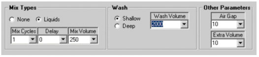
Figure 5. Special controls for mixing, tip washing, air gap and extra volume.
To perform the extraction operation shown in Picture 1., the chemist would:
- Place the reactor and receiver plate with a filter on the robot deck
- Select the "Transfer 24 well to 24 well," and hit the "Load Worktable" button.
- In Controls 2, select Rack 3 of the Source control and drive the tip to just above the meniscus.
- In Controls 2, select Rack 6 of the Destination 1 control and drive the tip to inside the filter plate and enter the Volume to transfer.
- In Controls 5, select the 24 wells of Rack 3 and hit Start.
- Go get a cup of coffee.
The setup, or programming of the robot (steps 1-5), takes about 45 seconds. The cycle time for each transfer is around 15-20 seconds so the entire 24 well extraction operation takes less than 9 minutes. As the robot moves through each of the wells, the color of the wells in the selection control 5 changes from green to blue. The repeat button, which might be used for a second extraction, changes the blue wells back to green and starts the process again.
A separate control (shown in Figure 6.) is available under the Options pulldown menu, which allows other interactions with the robot. These include system solvent selection, syringe purging and direct access to low level machine commands.
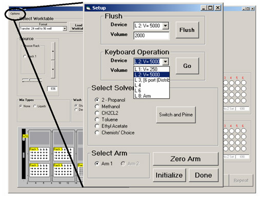
Figure 6. Options Control for solvent selection and access machine commands.
In addition to the 24 well to 24 well transfer program described above, we have implemented eight other transfer programs. The worktables are shown in Figure 7. Program 1 (Transfer: 96 well to 96 well) works essentially the same as Program 2 (Transfer: 24 well to 24 well), except on a 96 well microtiter format. Program 3 (Transfer: 24 well to 96 well) transfers samples from 24 well plates into the quadrants of a 96 well microtiter plate. Because LC/MS and Flow NMR are all run in our labs from 96 well microtiter plates, Program 3 is used primarily for preparing analytical samples. Program 4 (Transfer: 96 well to 24 well) allows transfer of the quadrants of a 96 well plate to individual 24 well plates. Programs 5, 6 and 7 (TLC: 96 well, TLC: 24 well and TLC: 4 X 24 Well) are for spotting TLC plates. When these programs are used, the third carrier is replaced with a stepped TLC plate holder. The heights for the TLC plates are preset and not set by the user. A picture of the TLC rack in use and a sample TLC plate are shown in Pictures 2a. and 2b. Program 8 is used to transfer samples returned from the HPLC prep lab (in a Gilson Rack) to our submission vials in a 24 well format. Finally, program 9 is used for reagent addition from EPA type vials to 24 well reactors. A color map is shown in the program 9 screen to indicate the one-to-many relationship for reagent addition. Full pictures of the screen layouts along with pictures of the robot are included in the supplemental material.
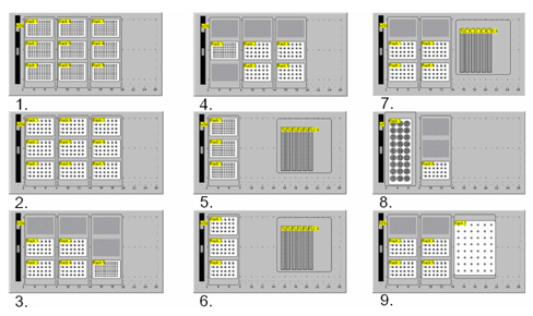
Figure 7. Available worktables. 1.) Transfer: 96 well to 96 well. 2.) Transfer: 24 well to 24 well. 3.) Transfer: 24 well to 96 well. 4.) Transfer: 96 well to 24 well. 5.) TLC: 96 well. 6.) TLC: 24 well. 7.) TLC: 4 X 24 Well. 8.) Transfer: Prep Tubes to 24 well. 9.) Reagent Addition: 24 well.
2a. 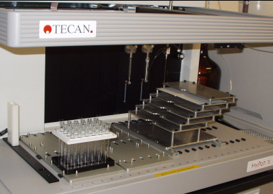
2b. 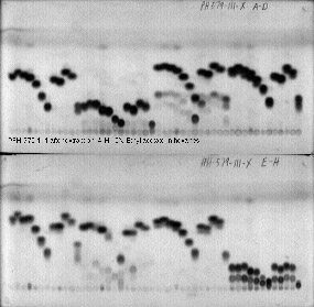
Pictures 2a. TLC rack in use 2b. Sample TLC plates, 96 samples
Although, for simplicity sake, we chose to describe our Transfer software for the TECAN MiniPrep, we have also implemented a similar system on the TECAN Genesis 150.4 The Genesis is a one arm, eight tip liquid handling robot with roughly twice the deck space. The larger deck space allows us to implement two sets of source and destination racks. We have implemented the same transfers on the Genesis that correspond to worktables 1-7 (Figure 7.) on the MiniPrep. The Genesis is substantially faster for 96 well plates and can perform 96 liquid-liquid extractions with filtration in about 3 minutes. However, because we use 1 mL syringes to get accuracy for TLC spotting and the Genesis can only use 4 tips at a time for 24 well plates, the speed advantage is diminished for larger reactors. The only hardware modifications to the Genesis are replacement of the solvent feed and drain lines with Teflon tubing. The Genesis 150, in the process of a 96 well extraction and filtration, is shown in Picture 3.
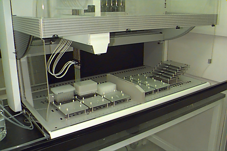
Picture 3. Genesis 150 performing a liquid-liquid extraction followed by filtration.
Summary. Historically, the use of liquid handling robots in the synthetic chemistry lab has required writing fairly complex programs to accomplish even the simplest of tasks. Changing variables like a height or a transfer volume meant writing a new program or modifying an old one. We decided to remove the difficult programming from the end users and let it be done by a few individuals who actually like to program and also know how chemistry is done. By understanding and implementing the fundamental manipulations necessary in organic synthesis, we have developed fast, flexible, easy to learn and easy to use, robotic systems that fit seamlessly into a medicinal chemistry environment.
Acknowledgment. We thank Bob Dyckmann of TECAN for his help in obtaining the Express software from Cavro. We also thank the members of the Lead Generation Chemistry group of Lilly RTP for testing, use and suggestions related to the development of the Transfer software.
Methods. The software interface for the Tecan Genesis robots was written with Microsoft Visual Basic 6.0 using the Tecan toolkit API provided in the Setup and Service software package (v 3.1). Worktables were defined with the Complete Worktable editor, also provided with Setup and Service. Microsoft Visual Basic 6.0 was also used to produce interface software for the Tecan MiniPrep robots. API's used to drive the robot, in addition to some visual aspect, were taken from the Express (v1.0) package, marketed by Cavro. Express was also used to layout the worktables used by the interface software.
Microsoft Windows 2000 was used as the development environment, with deployment packages created using functions built into Microsoft Visual Basic 6.0 Professional. These packages were then deployed over the local network to the robot controlling computers running either Windows NT or Windows 2000.
References and Notes.
- Hughes, P. F.; Graham, T. H.; Mendoza, J. S. Array Reactors for Parallel Synthesis, J. Comb. Chem.; 2004, 6, 308-311.
- Most solvent and reagent solution additions are performed with the Eppendorf Repeater Pipette.
- Listings of most commercially available equipment for parallel synthesis can be found on the web at sites such as http://www.combichemlab.com/website/files/home.htm, http://www.combinatorial.com/instruments.html and http://combichem.net/.
- Tecan U.S., Inc., 4022 Stirrup Creek Road, Suite 310, Durham, NC 27703, http://www.tecan-us.com